
Azimuth (AZ) Elevation (EL) Satellite Rotor Controller for Ham Radio
(THIS PAGE IS IN PROGRESS but contains enough detail to get you going)
Building a working home brew tracker has been a two-year
adventure that helped to highlight just how little I know about
electronics. I am not an engineer, I
majored in Public Policy and have had no formal electrical / electronics
training. Thus began the tinkering. I had two Alliance U-100 rotors, get yours from Norm:
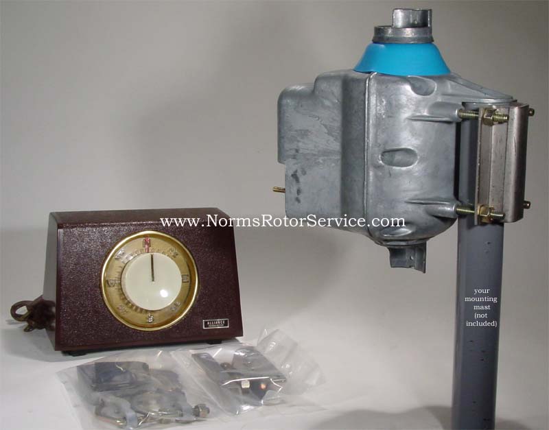
I first came upon the KH6HAK rotor.
I first came upon the KH6HAK rotor.
This looked like a great rotor, but the programming was for
a stamp and in Basic. I grew up on C++
and PHP. He provides a great reference for waterproofing and mounting your rotors, be sure to check it out when deciding how to hold the rotors together.
I then tried the K3NG model. At the time, it didn’t quite have the pulse rotor coding where I wanted it so I had to look for something else. (Though these are great rotor projects, they weren’t suited to my more limited skill set).
I then tried the K3NG model. At the time, it didn’t quite have the pulse rotor coding where I wanted it so I had to look for something else. (Though these are great rotor projects, they weren’t suited to my more limited skill set).
I then struck gold with N9CX, Bill Erwin.
He was using an ATMega32 programmed in C that used Alliance
U-100’s and would auto calibrate to each rotor.
This meant I could do the KH6HAK modification to make pulses roughly 5
degrees each (increasing the accuracy), and it would work with many of the
components I already had.

(Photo from KH6HAK) See how to improve pulse accuracy from KH6HAK, here.
I ended up using an eye hook and JB Weld Steel stick rather than cutting a screw in half.
Before describing the project in detail, I want to say a
special thanks to Bill Erwin who was instrumental in getting the project
working and very patient in addressing my many challenges during the course of
the project. He was a great Elmer and
mentored me along the way as I fried transformers, optocouplers, and even an
ATMega chip. After a few months of
emails and trial and error, the project is working and I am confident that I
could not have done it without his guidance.
He didn’t just provide the code and schematics, he helped me tailor the
project to my equipment and goals.
Get started
- Read over Bill Erwin's page here.
- His schematic is not the same as mine, I took a slightly different approach using bipolar capacitors and pre-made relays, described below.
- His programming and connections to the micro controller are identical to mine (because I used his format).
- Download his HEX file here.
- Check the checksum with this.
- I noticed that using Apple Mail, the checksum never matched and I had to directly download from the website or Gmail Website versions of the Hex file. Be aware if you email the file it may be corrupted by email systems like mine was.
- Review this site and start building up your rotor.
Where the Mega32 Lives
It may work better for some to build the entire
interface on their own. I love
development boards and used this one:
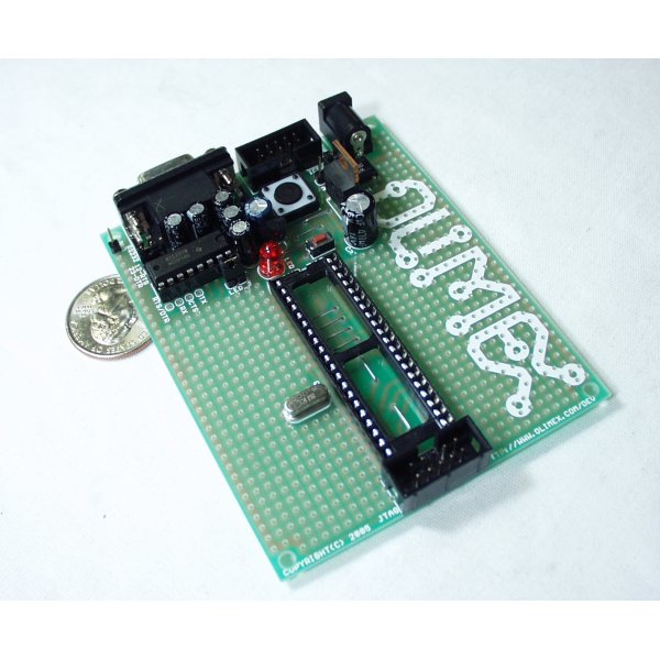
It is a clean interface and already has voltage and ground
rails for easy development.
Insert the ATMega32 into the board and you are ready to
program.
You should be familiar with the pins on the chip the numbers I refer to are on the interior of the chip.

You should be familiar with the pins on the chip the numbers I refer to are on the interior of the chip.
Program the Chip

You also have to install AVRDude (This link will explain how to do the install in a step by step fashion).
Then connect the cable from the USBTiny to the header on the
board near the serial port and power the board (I program with the board powered
so I don’t have to use the USBTiny jumper to provide power over USB. My MacBook Pro didn’t provide enough power
over the port and it kept disabling it).
Open up Terminal (command prompt) and type the following to
set the fuse bits (only needs to be done once and it stays on the chip)
avrdude -c usbtiny -p m32 -U hfuse:w:D9:m
avrdude -c usbtiny -p m32 -U lfuse:w:FF:m
Then program the chip with the hex file (substitute your
path, this is a Mac format)
avrdude -c usbtiny -p
m32 -U flash:w:"/Users/AK4FA/Desktop/andrew.hex"
The programmer should verify it successfully copied over the
firmware.
This tutorial does a good job covering AVR programming
Powering the board
The development board can take a range of voltages through
the power connector. You can use a
connector to power the board or solder power inputs directly into the
board. I chose to take a 12v transformerto power all of the internals.

The 12v transformer goes into my filtering circuit (not sure
if that is what it is called, but I got the idea off of the KH6HAKpower
supply. I substitute a 9v regulator for
the 5v regulator in the KH6HAK design.
Now that I have 9v DC coming out, I connect that directly to the development
board input in order to use the existing circuitry to further step down the
voltage to 5v at the rails. If you have
a 9v direct source, that would work too, the step down voltage just wastes
energy as heat.

The regulator above should say 7809 not 7812 (for some reason my library was not cooperating, this should step down to 9v, not 12v).
Above is the schematic for the power circuit I put on an auxiliary board, the 12v transformer goes into a molex header and Pin 1 is the ground of the transformer to the ground of the auxiliary board, pin 3 is the 12v source into the circuit. The 12v then goes into a diode, a voltage regulator, and finally out to another molex header which I used to take 9v to the development board with the micro controller. There is an led to that goes out to the front of the case to show that the circuit is powered. The two capacitors are filter capacitors, one is 4700uf the other is 1uf. The capacitors are polarized. The output of that molex connector is a direct input to the development board's power input (the development board has an additional regulator that steps the voltage down to 5v and then supplies that voltage to the chip and the rail on the development board).
Switches
The controller has switches to go CW, CCW, Up, Down,
Calibrate, and AutoTrack. When
prototyping, I soldered header pins to the development board and used a jumper
wire to connect the pins to ground for testing.
Once I boxed the project, the pins are in a normally high state, and the
switches need to be momentary normally off switches that short the ATMega pin
to ground in the following way:
Pin 35 is shorted to ground to engage the AutoTrack feature
Pin 36 is shorted to ground to engage the Calibration
feature
Pin 37 is shorted to ground to rotate down.
Pin 38 is shorted to ground to rotate up.
Pin 39 is shorted to ground to rotate CW.
Pin 40 is shorted to ground to rotate CCW.

As you can see in the final version I used push button
Momentary On, Normally Off switches for the Auto and Calibrate and Momentary
On, Normally Off toggle switches to do the rotation. Use whatever switches you like, it is only
important that they connect the ATMega pin to ground.
You may also want to include a power switch for the
transformers, or just one to cut the AC power where it goes in the box.
The LCD
Wiring the LCD can be somewhat frustrating, I ended up using
a ribbon cable but learned the hard way that saving time with prewired
connectors doesn’t always save time. I
ordered from Mouser a prewired header.


I thought that I could put matching header pins on the board
in the correct configuration and it would work

Unfortunately, the prewired connector shorts pin 5 to ground
on the LCD, which means that the display will never work. I cut the contact pin on the prewired header
for pin 5, and directly soldered an additional wire to pin 5 to make the
connection to the micro controller. This
solved the LCD problem I created for myself.
The LCD Pins should be paired with the following ATMega
pins.
·
LCD 11 to ATMega 22
·
LCD 12 to ATMega 23
·
LCD 13 to ATMega 24
·
LCD 14 to ATMega 25
·
LCD 4 to ATMega 26
·
LCD 5 to ATMega 27
·
LCD 6 to ATMega 28
·
LCD 1 to 5v
·
LCD 2 to Ground
With the prewired board, the potentiometer is already
connected. Check out the data sheet on
the connector to see the pinout for the header.
Wiring the Rotor
The rotors require a 24v source (15v stiff). I used this but I don't believe it meets the 15v stiff current source recommendation of Bill Erwin.

I interconnected the ground wires between the rotor transformer
and the 12v transformer.
This made sure the optocouplers work.
You will need four relays, I already had a set from an Arduino project.

For this set, connect to the development board’s 5v rail and
ground connection, as well as the ATMega
·
Relay CW ATMega Pin 1
·
Relay CCW ATMega Pin 2
·
Relay Up ATMega Pin 3
·
Relay Down ATMega Pin 4
I then split the rotor 24v input and fed it into the relays.
The outputs went to pins 1 and 2 on the Alliance U-100.
Pin 3 on the Alliance U-100 was the ground, and Pin 4 is the
pulse contact.
Pins 1 and 2 need to be connected together with a bipolar
capacitor to power one leg of the motor out of phase.

Again, I use molex headers to essentially tie the output from the relays to the bipolar capacitors and then send that power out to the rotors. These two circuits are identical, except I made a ground connection on one of them to tie the rotor ground in to the circuit ground. The capacitors have to be bipolar.
This unit takes a 5v input from the common rail on the development board through another molex header. The LED side of the optocoupler is the micro controller side. The molex header titled Rotor Pulses takes the output back to pins 20 and 21 of the ATMega 32. In the lower right, that molex header connects to terminal 4 on the AZ and EL rotor pulses, and then back to ground. This way the circuits stay electrically separate and pass the pulses. The external LED's go to the front of the case to indicate the pulses.
Make sure to keep your AZ and EL pulses and micro controller outputs matched up or you will read AZ pulses on the EL input.


In Mac Doppler:
Pulse Contacts
In order to determine where the rotor is, the micro controller needs to read the pulse contacts off of terminal 4 on the U-100.
Because we have both 24v and 5v, we need to use an optocoupler, or isolator to keep the circuits electrically separate.
The AZ pulse from the optocoupler goes to Pin 20 on the ATMega32
The EL pulse from the optocoupler goes to Pin 21 on the ATMega32

This unit takes a 5v input from the common rail on the development board through another molex header. The LED side of the optocoupler is the micro controller side. The molex header titled Rotor Pulses takes the output back to pins 20 and 21 of the ATMega 32. In the lower right, that molex header connects to terminal 4 on the AZ and EL rotor pulses, and then back to ground. This way the circuits stay electrically separate and pass the pulses. The external LED's go to the front of the case to indicate the pulses.
Make sure to keep your AZ and EL pulses and micro controller outputs matched up or you will read AZ pulses on the EL input.
Building a Board
I enjoy etching PC Boards, this page will teach you how to do it.
I laid out the board in Eagle
Etched it
Nail polish and sharpie cover up areas that were overexposed.
This is the drilled board
This is the board with components.
- Lower Right the bipolar capacitors that connect the output from the relays to the actual rotor.
- Middle - optocouplers are under the large capacitor, the molex headers above and below connect to the micro controller and the rotor pulse contacts.
- Top Right, inputs from the 12v transformer get converted and output to the 9v development board input (top middle molex). 5v is then brought back into the board on the top left molex connector coming from the development board rail.
- It would have been easier to do this all on the development board, but I am not neat enough to get it all to fit.
- The dangling wires are the LED's for the pulses and power indicators.
- I used a leftover heat dissipation foil on the voltage regulator.
The optocouplers somehow got mirrored in my schematic, so they are mounted from underneath the board (oops).
Connect TX to RX
On the development board, you need to connect the serial connector MAX232 chip to the ATMega32 chip.
- Pin 10 on the MAX232 goes to ATMega32 Pin 15
- Pin 12 on the MAX232 goes to ATMega32 Pin 14
The ground connection is already made on the board.
Computer Interface
I use MacDoppler as my program of choice. While the original version did not work with MacDoppler, Bill Erwin was kind enough to tweak his code to get the program working with MacDoppler.
Use a straight through RS232 serial cable to connect to the development board.
Use a straight through RS232 serial cable to connect to the development board.
In Mac Doppler:
- Select GS232B as the rotor type and 9600 baud.
- It is 1 stop bit, no parity if you are testing the program in a terminal or emulator
- Send W010 070 to the controller and it will orient itself 10 degrees and 70 elevation.
- MacDoppler does this automatically.
- I would assume that other software that has output in the 232B format would also work.
Box Considerations
You will want some type of disconnect to attach the rotor control cable to the control box.
I used a connector like this


I took the power supply from an old computer and got its power connector to make my AC connections to the transformers.
You will also want to bring the serial port input out of the box (or arrange the circuit so the board port is accessible.
Below you can see the Pulse LED's in yellow are beside the red power LED, which is on.
The Auto button is blue, below it is the Calibrate button in black.
The metal toggle switches control the rotors in manual mode.
This is an old dell computer case i cut up to mount the project.
Parts
This is a list of most of the parts
- Two Alliance U-100 Rotors
- Development Board
- ATMega32L-8PU (any version of the ATMega32 full size will work).
- 12v Transformer
- 24v Transformer
- 1N4004 Diode
- Molex Headers and connectors and pins
- 7809C Voltage Regulator
- 4700uf Capacitor
- 1 uf Capacitor
- Resistors (3 for LED's)
- LEDs (I used these, pick your favorite colors for pulses and power).
- Momentary On Switches (this is just an example)
- Toggle Switches (This isn't the exact one I used but it would work, center needs to be off).
- LCD Header
- LCD Screen
- Header Pins
- Relays
- 220uf Bipolar Capacitors (rated at 50 volts to handle the transformer)
- 4n25 Optocouplers
- Rotor Connector
- A board to put it all on whether you cram it into the development board, etch your own or use perf board
- Miscellaneous case, power connector, hookup wire, solder